Hack: Removing Google Home Mini Microphones
Last updated: Mar 25, 2020
I had a problem. I love music, and I love techonology, but not Big Brother. Shouldn’t tech be responsible, free (as in freedom), and in our hands? Mustn’t there be a way to bring audio in on the cheap without the big G smuggling itself in as well? I did some thinking. This was my dissonance. The desire to implement the Google Home ecosystem cheap and seamless wireless audio and (maybe) smart assistant, and a healthy dose of paranoia (toss a stone and find dozens of articles).
I went ahead and decided to reconcile the two. The Google Home Mini is an excellent middle ground between dollar store bluetooth speaker and entry level Sonos or IKEA smart speaker. They’re cheap, probably due to Spotify’s giveaway promo (~$20 on kijiji), ubiquitous, and can be painlessly controlled via centralized app once on wifi. So partly out of principle, partly out of paranoia, and partly out of curiosity, I acquired a few Google Home Minis and set out to remove the microphones. As an added bonus, I thought, I could check to see whether the switch was indeed a “hardware switch” as google claimed it is.
(Result: inconclusive. More later.)
The teardown of this device is not difficult, but I checked in with ifixit just in case. Right off the bat I could not get under the orange rubber with a spudger. A heat gun is far more effective. I just blasted it at 300℃ until the rubber just puckered and popped right off.
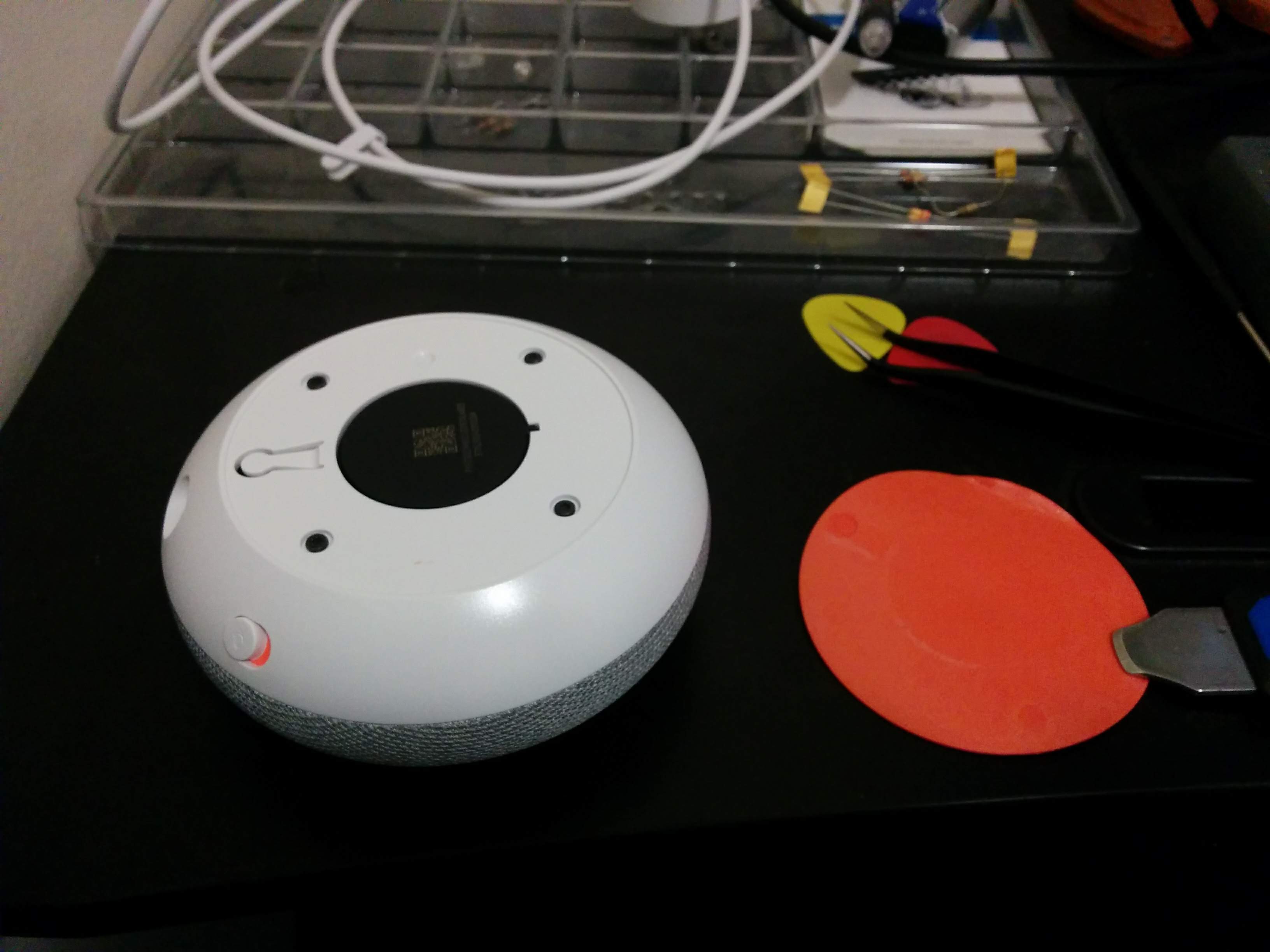
Once the rubber is gone, remove the 4 TT6 screws and lift the base off close to the microusb and switch side.
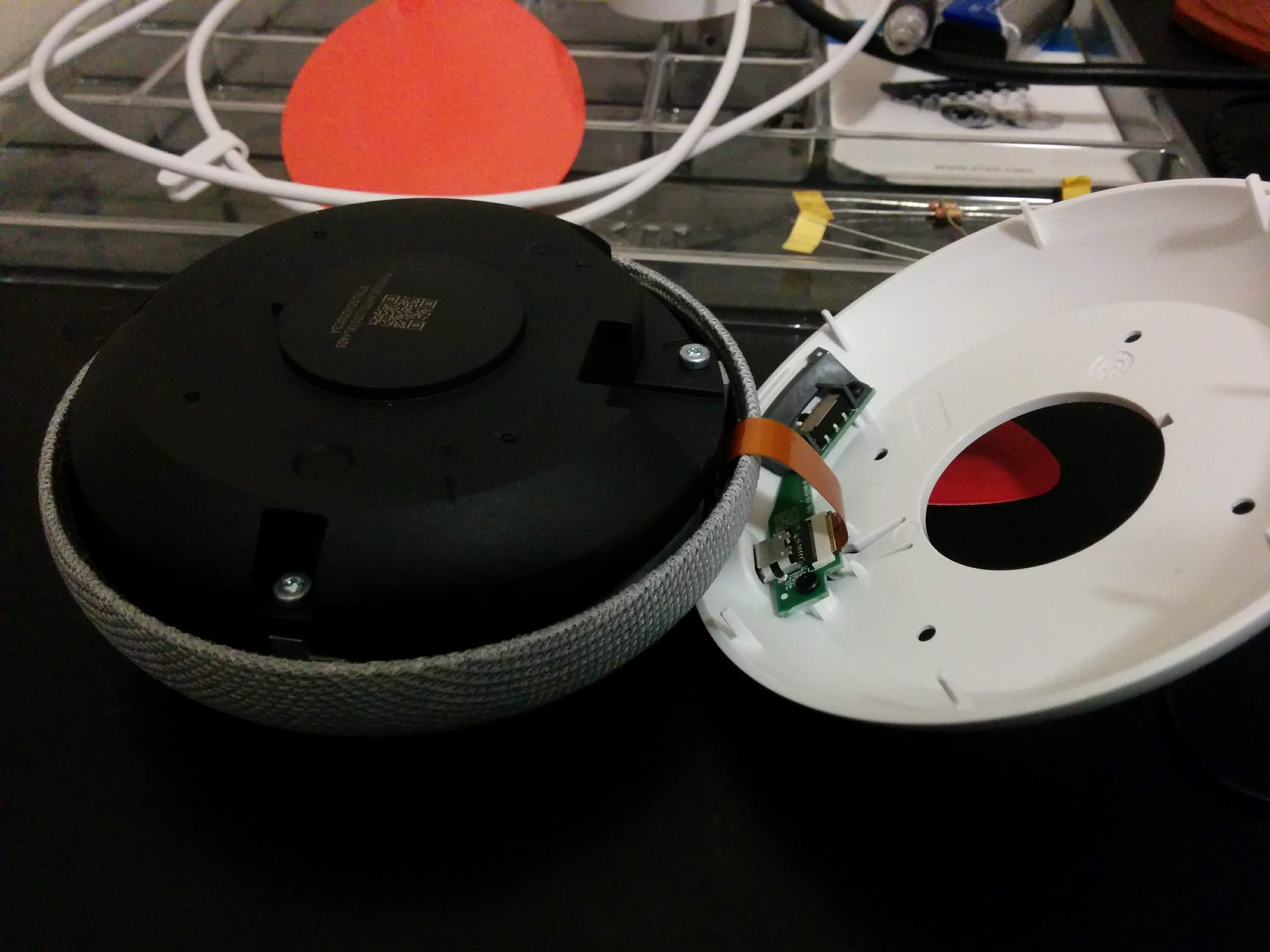
Pop the ribbon cable out by lifting the tab with a pair of fine-nosed tweezers.

Another 4 screws (TT9 this time) hold the speaker housing in place. Once those are removed, the speaker can be lifted right out, revealing the conal sound dispersion/heatsync piece.
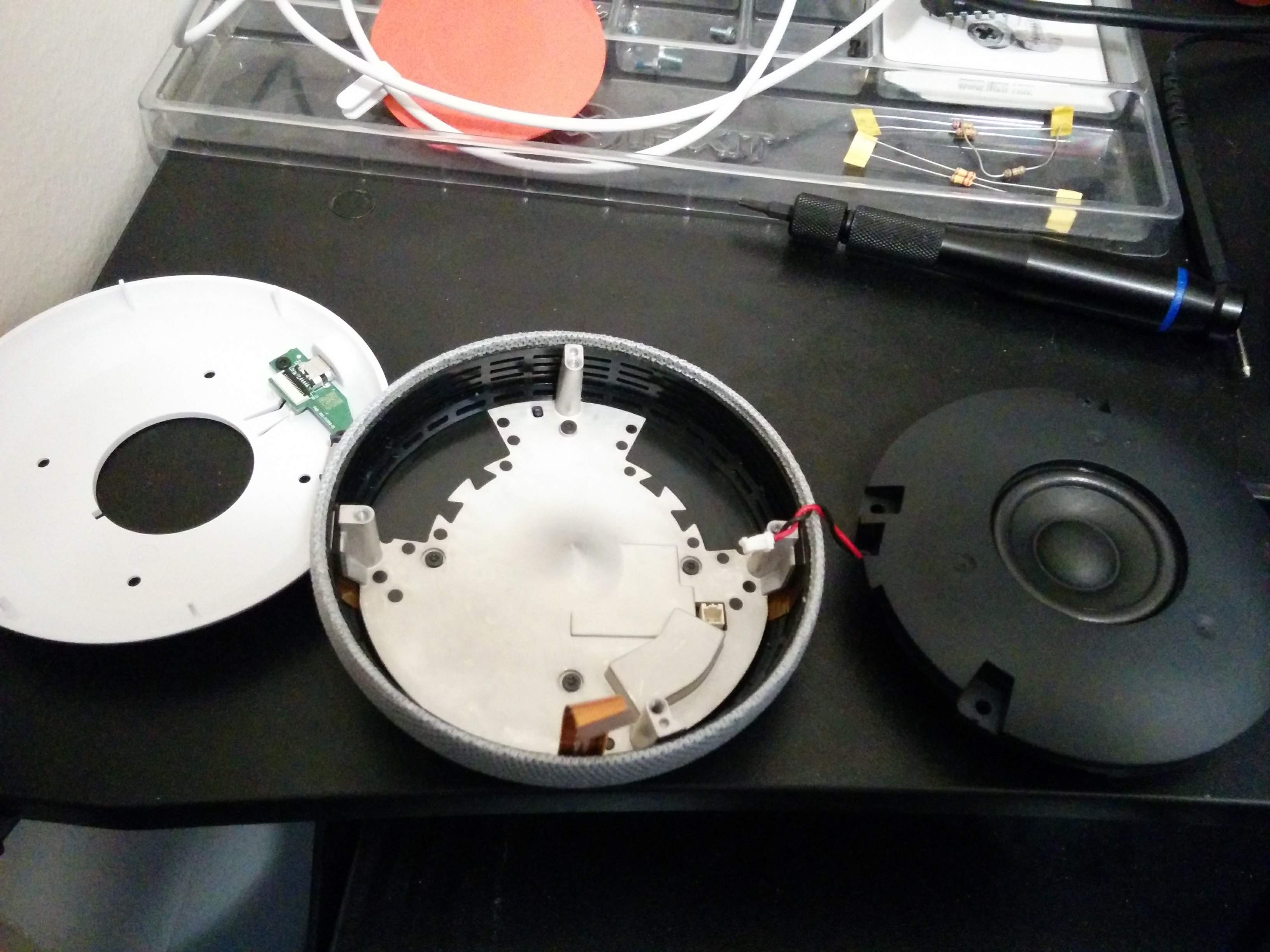
Unplug the speaker.
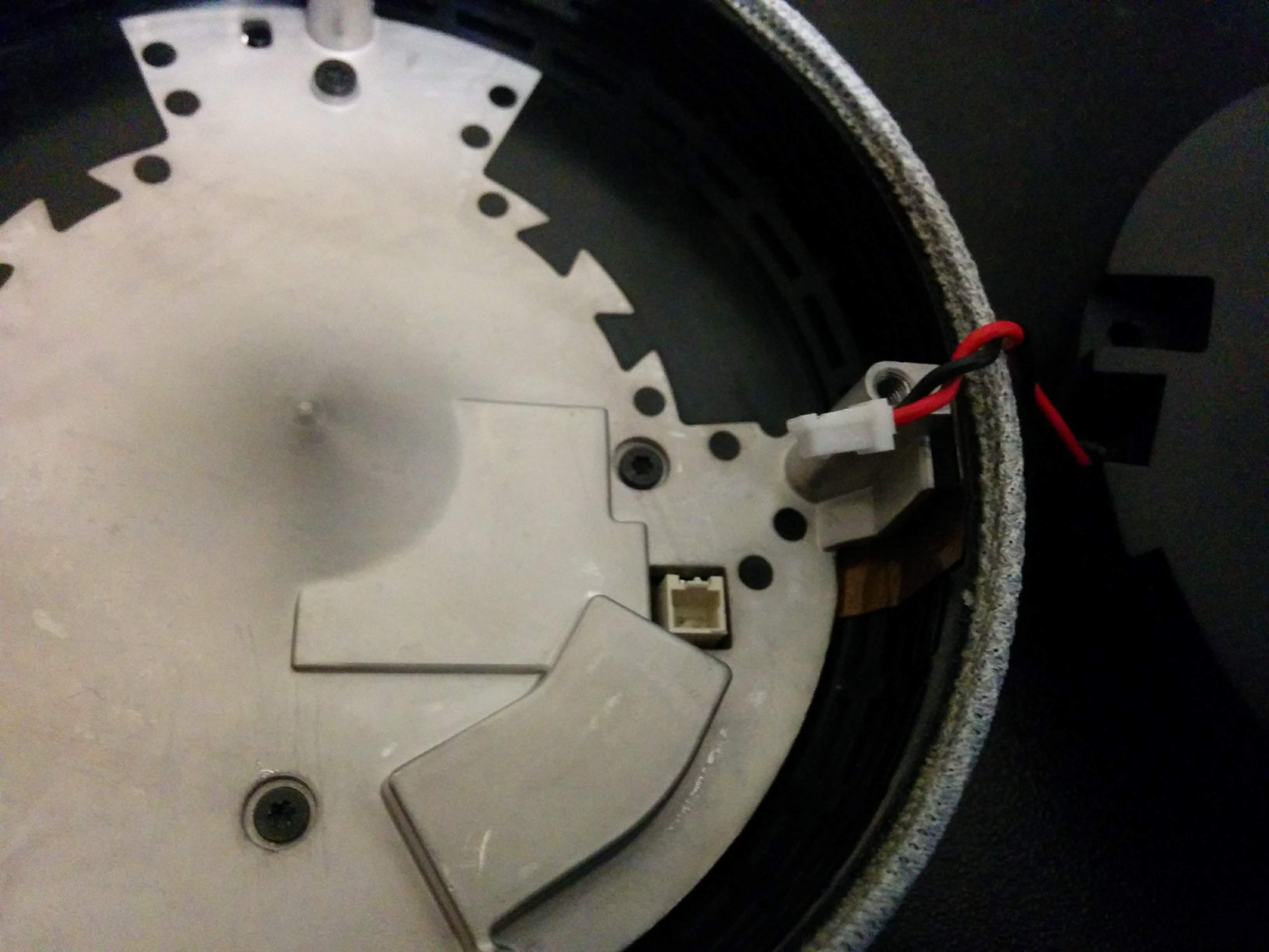
Yet another 4 screws (TT6) hold the heatsync/sound disperser down. Removing these reveal the pcb.

The target: 2 MEMS microphones.
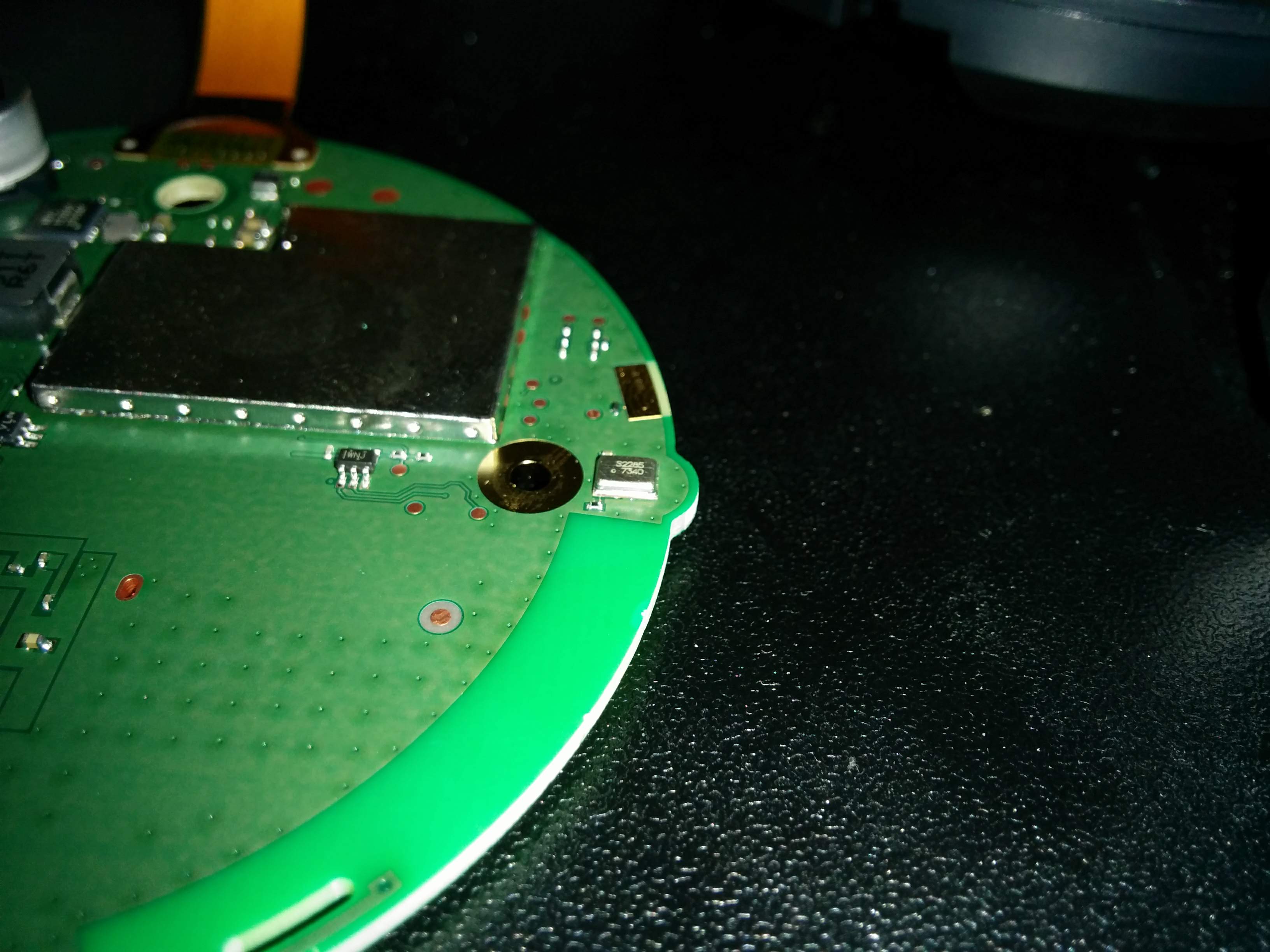
Blasting the chip at 500℃ to loosen the solder. At the right temperature it slides right off.
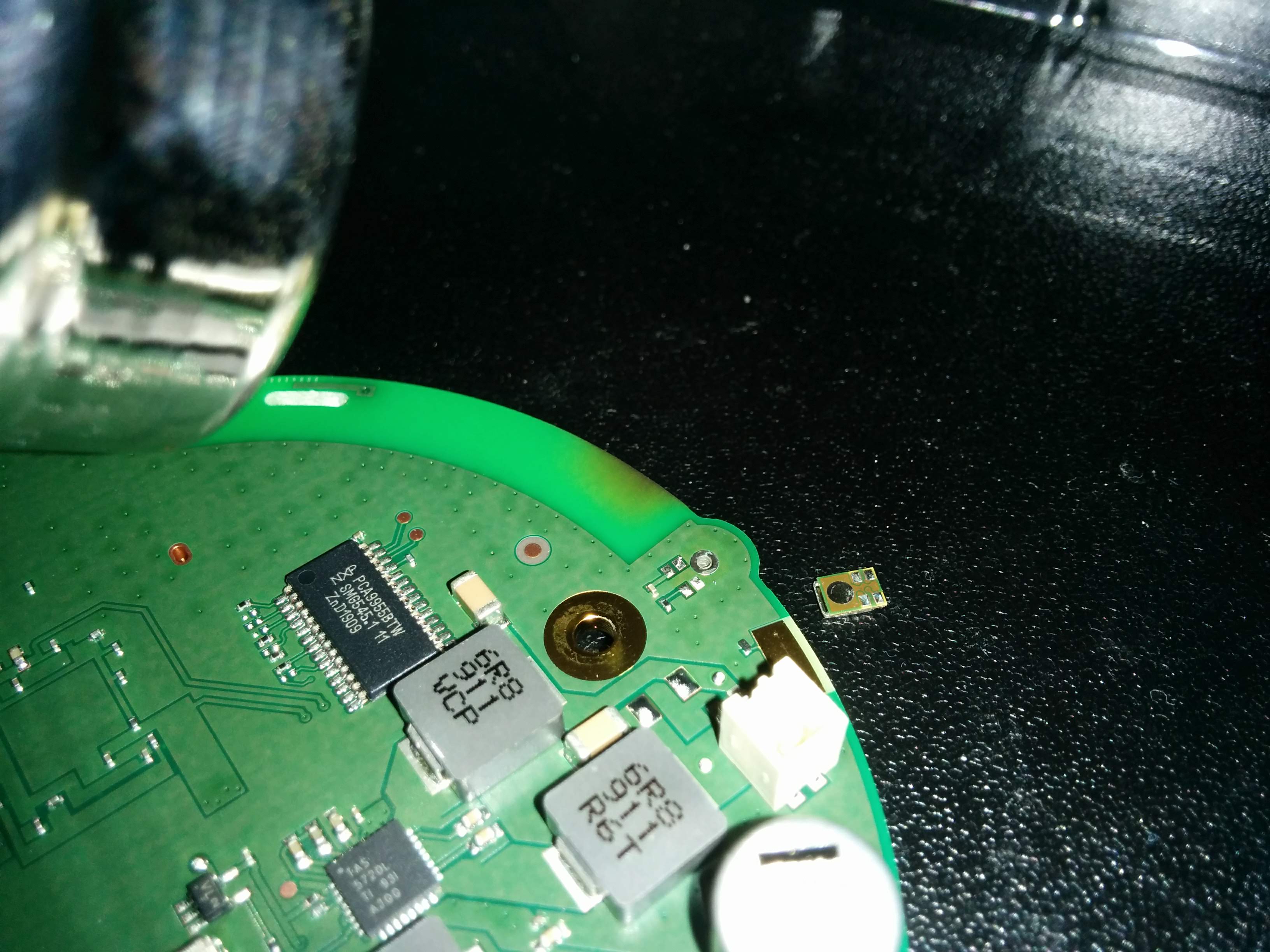
Results:

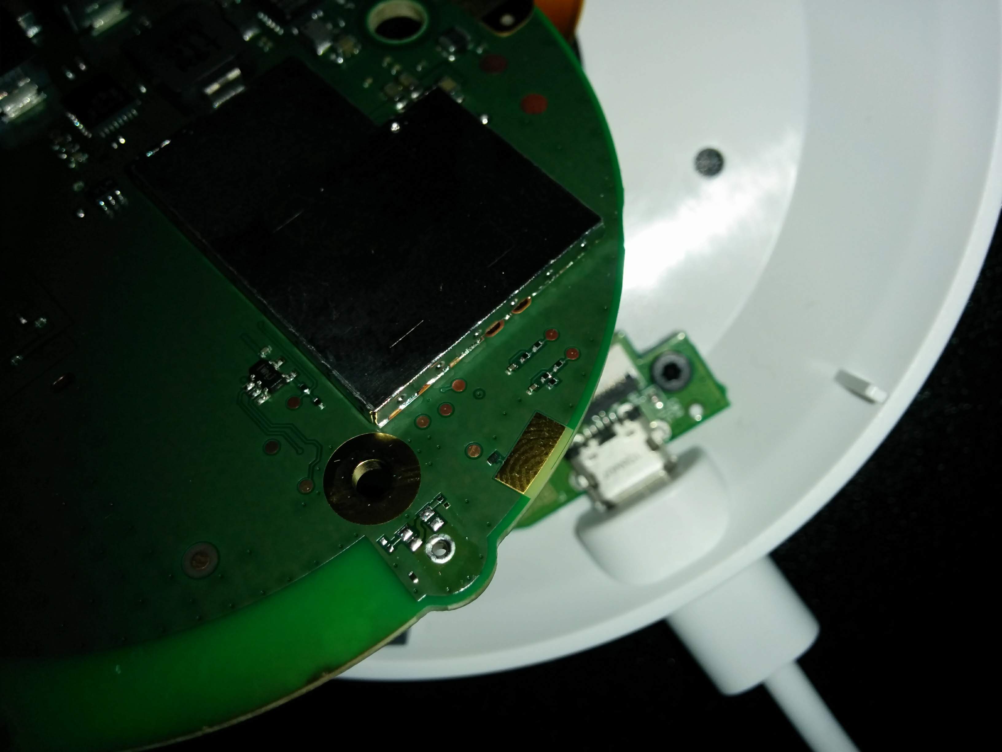
Exposed contacts after microphone removal:
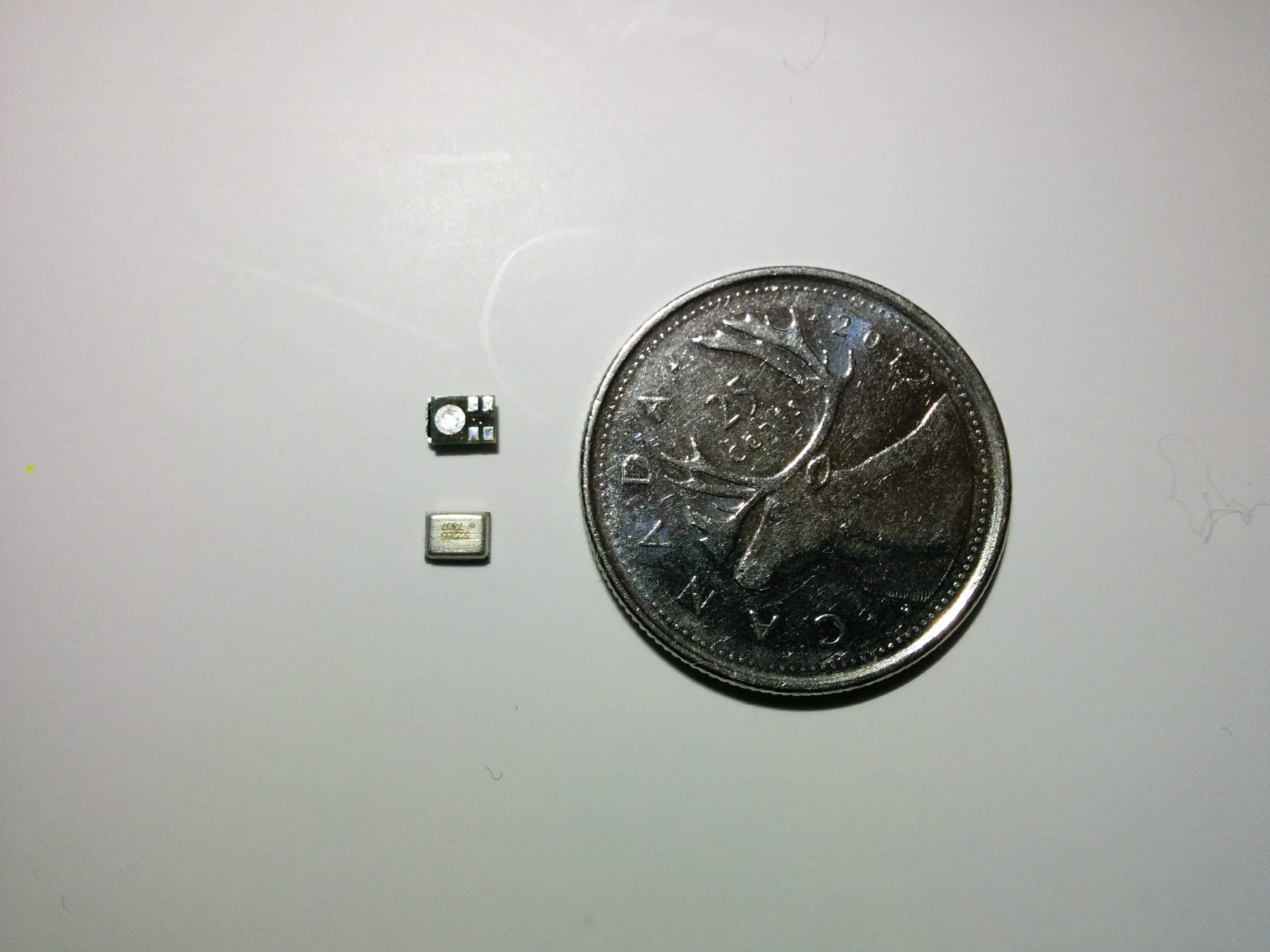
The microphones in question:
To test the hardware switch, I found this image courtesy of snektek.
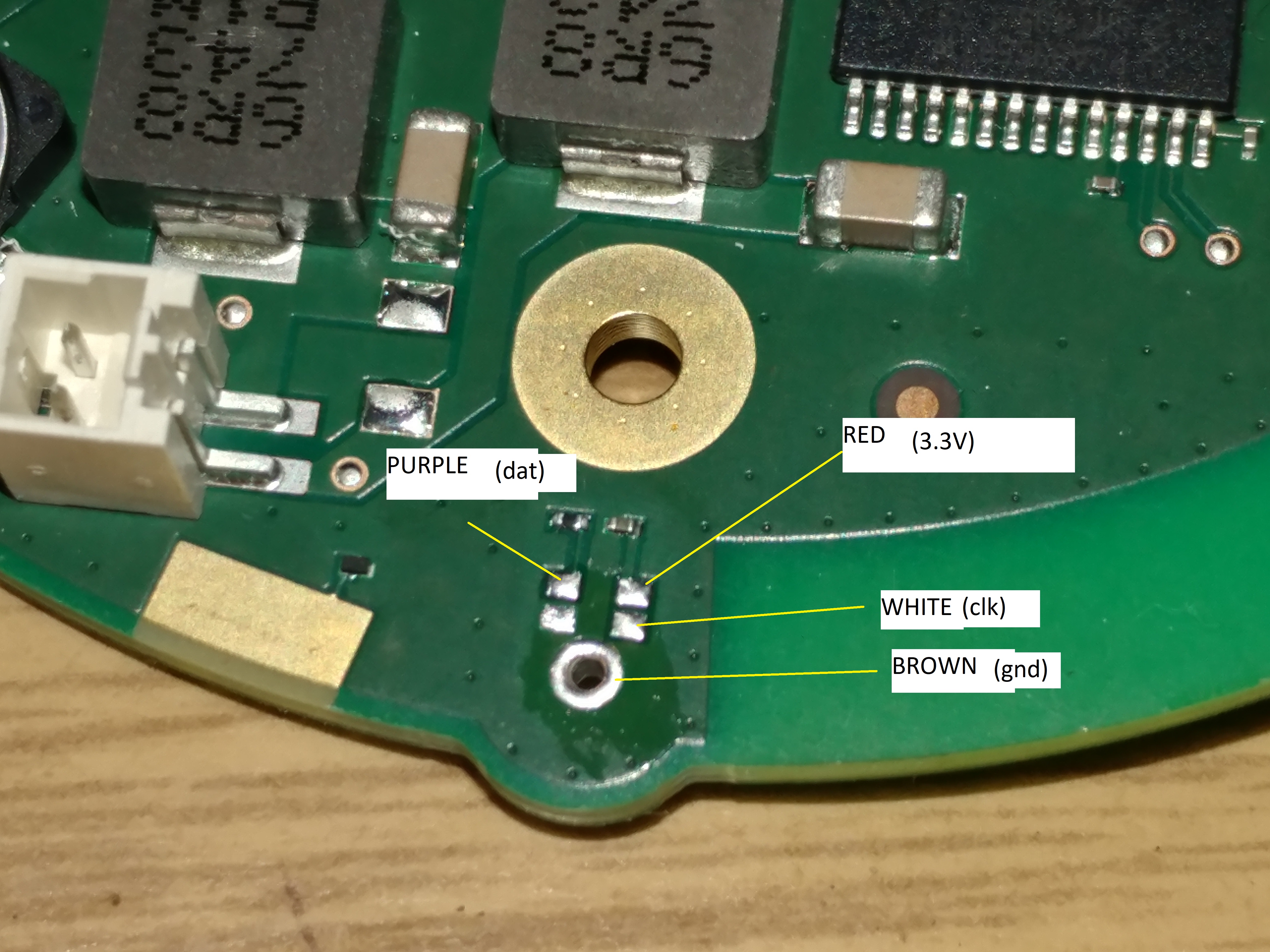
The mic receives 3.3v whether the switch is in the “on” or “muted” position. A hardware switch would cut voltage to the microphones, right? I’m no electrical engineer but I imagine one answer is likely: not necessarily.
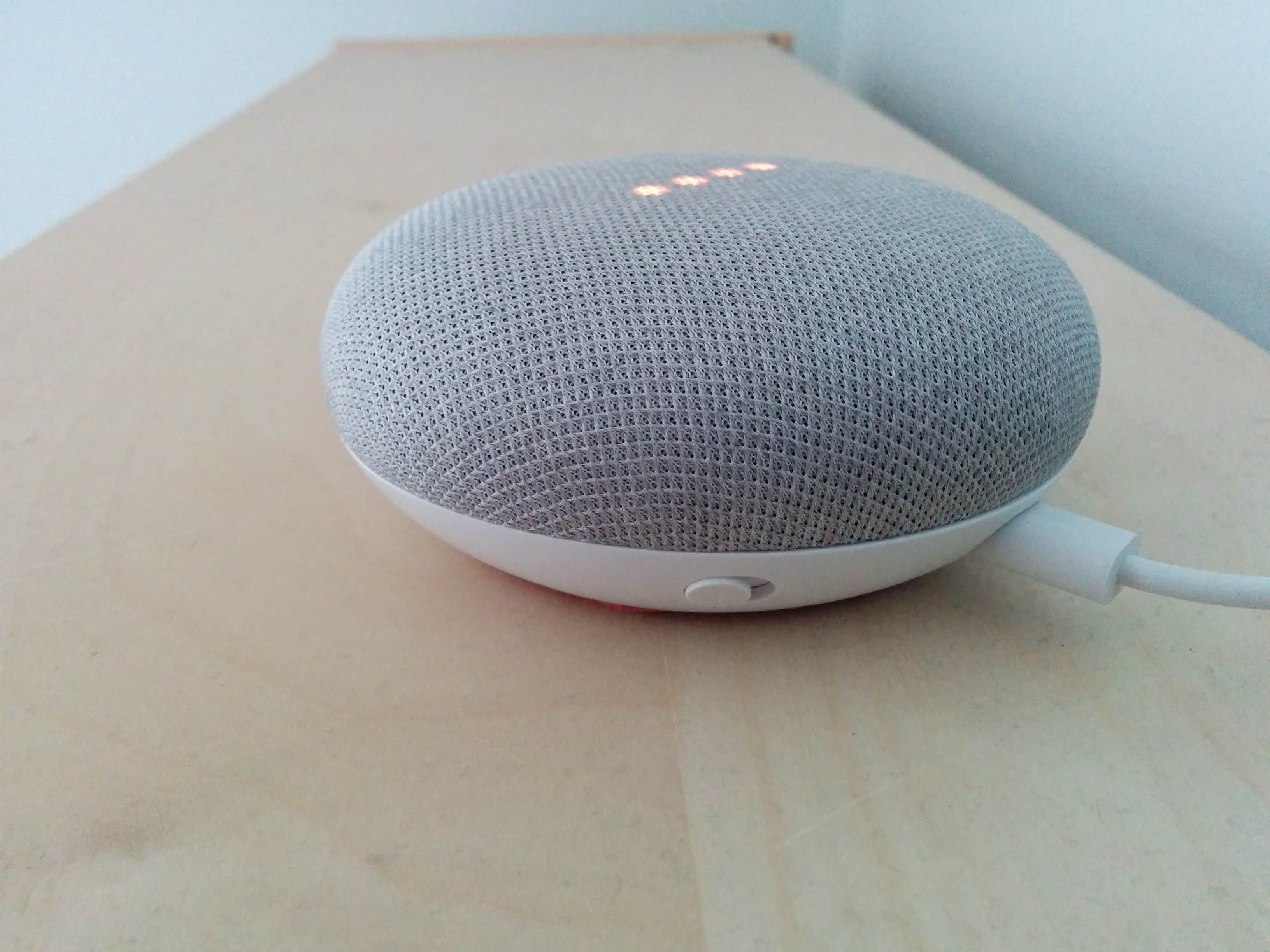
The orange lights and “the mic is off” message that appear when the switch is in the “mute” position began to appear after (mic removal) with the switch in either position. Without completely reverse engineering the device, I can only assume that the mechanism responsible for detecting mic muting detects a voltage drop somewhere in the mic circuit, and not necessarily at the mic itself. The switch could affect the circuit voltage between mic gnd and gnd, then triggering logic to activate the turn me on “mic is off” message. Although, if that were the case, we still wouldn’t see voltage, would we? If anyone has answers, please reach out to me.